Advertisement

Main menu

  • Home
  • Content
    • Current Issue
    • Accepted Manuscripts
    • Article Preview
    • Past Issue Archive
    • Video Articles
    • AJNR Case Collection
    • Case of the Week Archive
    • Case of the Month Archive
    • Classic Case Archive
  • Special Collections
    • AJNR Awards
    • Low-Field MRI
    • Alzheimer Disease
    • ASNR Foundation Special Collection
    • Photon-Counting CT
    • View All
  • Multimedia
    • AJNR Podcasts
    • AJNR SCANtastic
    • Trainee Corner
    • MRI Safety Corner
    • Imaging Protocols
  • For Authors
    • Submit a Manuscript
    • Submit a Video Article
    • Submit an eLetter to the Editor/Response
    • Manuscript Submission Guidelines
    • Statistical Tips
    • Fast Publishing of Accepted Manuscripts
    • Graphical Abstract Preparation
    • Imaging Protocol Submission
    • Author Policies
  • About Us
    • About AJNR
    • Editorial Board
    • Editorial Board Alumni
  • More
    • Become a Reviewer/Academy of Reviewers
    • Subscribers
    • Permissions
    • Alerts
    • Feedback
    • Advertisers
    • ASNR Home

User menu

  • Alerts
  • Log in

Search

  • Advanced search
American Journal of Neuroradiology

American Journal of Neuroradiology

ASHNR American Society of Functional Neuroradiology ASHNR American Society of Pediatric Neuroradiology ASSR
  • Alerts
  • Log in

Advanced Search

  • Home
  • Content
    • Current Issue
    • Accepted Manuscripts
    • Article Preview
    • Past Issue Archive
    • Video Articles
    • AJNR Case Collection
    • Case of the Week Archive
    • Case of the Month Archive
    • Classic Case Archive
  • Special Collections
    • AJNR Awards
    • Low-Field MRI
    • Alzheimer Disease
    • ASNR Foundation Special Collection
    • Photon-Counting CT
    • View All
  • Multimedia
    • AJNR Podcasts
    • AJNR SCANtastic
    • Trainee Corner
    • MRI Safety Corner
    • Imaging Protocols
  • For Authors
    • Submit a Manuscript
    • Submit a Video Article
    • Submit an eLetter to the Editor/Response
    • Manuscript Submission Guidelines
    • Statistical Tips
    • Fast Publishing of Accepted Manuscripts
    • Graphical Abstract Preparation
    • Imaging Protocol Submission
    • Author Policies
  • About Us
    • About AJNR
    • Editorial Board
    • Editorial Board Alumni
  • More
    • Become a Reviewer/Academy of Reviewers
    • Subscribers
    • Permissions
    • Alerts
    • Feedback
    • Advertisers
    • ASNR Home
  • Follow AJNR on Twitter
  • Visit AJNR on Facebook
  • Follow AJNR on Instagram
  • Join AJNR on LinkedIn
  • RSS Feeds

AJNR Awards, New Junior Editors, and more. Read the latest AJNR updates

Review ArticleNeurointervention

Intraluminal Flow Diverter Design Primer for Neurointerventionalists

Alexander A. Oliver, Yigit Can Senol, Cem Bilgin, Jeremy E. Schaffer, Ramanathan Kadirvel, David F. Kallmes and John M. Wainwright
American Journal of Neuroradiology April 2024, 45 (4) 365-370; DOI: https://doi.org/10.3174/ajnr.A8076
Alexander A. Oliver
aFrom the Department of Biomedical Engineering and Physiology (A.A.O., D.F.K.), Mayo Clinic Graduate School of Biomedical Sciences, Rochester, Minnesota
bDepartment of Radiology (A.A.O., C.B., R.K., D.F.K.), Mayo Clinic, Rochester, Minnesota
  • Find this author on Google Scholar
  • Find this author on PubMed
  • Search for this author on this site
  • ORCID record for Alexander A. Oliver
Yigit Can Senol
cDepartment of Neurologic Surgery (Y.C.S., R.K.), Mayo Clinic, Rochester, Minnesota
  • Find this author on Google Scholar
  • Find this author on PubMed
  • Search for this author on this site
Cem Bilgin
bDepartment of Radiology (A.A.O., C.B., R.K., D.F.K.), Mayo Clinic, Rochester, Minnesota
  • Find this author on Google Scholar
  • Find this author on PubMed
  • Search for this author on this site
  • ORCID record for Cem Bilgin
Jeremy E. Schaffer
dFort Wayne Metals (J.E.S.), Fort Wayne, Indiana
  • Find this author on Google Scholar
  • Find this author on PubMed
  • Search for this author on this site
Ramanathan Kadirvel
bDepartment of Radiology (A.A.O., C.B., R.K., D.F.K.), Mayo Clinic, Rochester, Minnesota
cDepartment of Neurologic Surgery (Y.C.S., R.K.), Mayo Clinic, Rochester, Minnesota
  • Find this author on Google Scholar
  • Find this author on PubMed
  • Search for this author on this site
  • ORCID record for Ramanathan Kadirvel
David F. Kallmes
aFrom the Department of Biomedical Engineering and Physiology (A.A.O., D.F.K.), Mayo Clinic Graduate School of Biomedical Sciences, Rochester, Minnesota
bDepartment of Radiology (A.A.O., C.B., R.K., D.F.K.), Mayo Clinic, Rochester, Minnesota
  • Find this author on Google Scholar
  • Find this author on PubMed
  • Search for this author on this site
  • ORCID record for David F. Kallmes
John M. Wainwright
eMIVI Neuroscience (J.M.W.), Eden Prairie, Minnesota
fThe Henry Samueli School of Engineering (J.M.W.), University of California, Irvine, California
  • Find this author on Google Scholar
  • Find this author on PubMed
  • Search for this author on this site
  • Article
  • Figures & Data
  • Info & Metrics
  • Responses
  • References
  • PDF
Loading

Abstract

SUMMARY: The clinical use of flow diverters for the treatment of intracranial aneurysms has rapidly grown. Consequently, the market and technology for these devices has also grown. Clinical performance characteristics of the flow diverter are well-known to the clinician. However, the engineering design principles behind how these devices achieve ideal clinical performance are less understood. This primer will summarize flow diverter design parameters for neurointerventionalists with the aim of promoting collaboration between clinicians and engineers.

ABBREVIATIONS:

DFT
drawn filled tubing
FD
flow diverter
ID
inner diameter
PPI
pics-per-inch

During the past decade, flow diverters (FDs) have grown into a standard endovascular approach for the treatment of intracranial aneurysms. FDs have demonstrated excellent safety profiles and aneurysm occlusion rates in the clinic.1 Consequently, several FDs have achieved market approval, and many more devices are in development.2 While the clinical performance characteristics of FDs are well-known to the clinician, how the FD engineer achieves successful device performance is less well-understood. This primer will outline the basic FD design parameters available to the engineer and describe how their selection influences the characteristics of device performance for the practicing interventionalist.

Ideal FD

The generic term “flow diverter” describes devices that cover the aneurysm/parent artery interface to achieve aneurysm occlusion. Initially after placement, the device likely causes some degree of “diversion” of flow into the parent artery that otherwise would have entered the aneurysm, and the term itself is nonspecific and likely no more valid than terms such as “flow disruptor.” However, with time, tissue will grow over the aneurysm neck and the aneurysm will become occluded, and ultimately, the end goal is that all flow will be diverted away from the aneurysm sac. Furthermore, there now are both intraluminal and intrasaccular flow diversion devices; this review will focus exclusively on the former type.

In general, FDs are braided or woven stents deployed in the parent artery over the neck of the aneurysm. These devices aim to divert most of the blood flow past the aneurysm, resulting in blood stagnation and coagulation within the aneurysm sac. This diversion of flow with resultant intra-aneurysmal blood stasis theoretically forms a thrombus plug within the aneurysm cavity, hindering blood flow into the aneurysm. In the meantime, the device serves as a scaffold for endothelialization and neointimal growth over the aneurysm neck, ultimately occluding the aneurysm from blood flow.3 Overall, the ideal FD maximizes ease of deployment and aneurysm occlusion while minimizing the risk of complications.

Several interrelated FD performance characteristics contribute to clinical efficacy. The ideal FD maximizes stagnation of blood flow within the aneurysm sac as well as rapid endothelialization and neointimal growth over the aneurysm neck.3 The major design goals are listed here briefly and then discussed in detail below in relation to the engineering principles underlying design choices. First, optimized FD apposition to the parent artery wall after delivery benefits both saccular blood stagnation and endothelialization.4,5 Additionally, tight FD wall apposition can reduce the risk of thrombus formation between the wires of the device and the arterial wall, which could lead to the blockage of perforator arteries and stenosis. Better FD wall apposition can be achieved by improving the flexibility of the device6 and, in some cases, the radial opening force (or chronic outward force) of the device, which is the force exerted by the device expanding outward on the artery wall.7 In straighter vessels, increased opening force theoretically pushes the wires tighter to the vessel wall. However, in tortuous anatomies, device flexibility may be more advantageous than radial opening force for maintaining wall apposition. Therefore, wall apposition is ultimately the result of numerous factors. Second, the ideal FD minimizes the risk of complications such as thromboembolism induced within the lumen of the device or the occlusion of perforator arteries adjacent to the aneurysm. Third, the ideal FD eases delivery for the interventionalist.

FDs that can be deployed through smaller inner diameter (ID) microcatheters are advantageous for advancing the microcatheter through the tortuous cerebrovasculature and may allow their advancement to more distal aneurysms. The current benchmark for FD delivery microcatheters is an ID of ≤0.027 inches,2 and the ideal FD should be deployed through a microcatheter this size or smaller. Reduced delivery force, which we are defining as the force required to track the FD through the lumen of the microcatheter, also eases delivery for the interventionalist. The ideal FD achieves suitable wall apposition as easily as possible for the interventionalist.8,9 Last, the FD needs to achieve a suitable degree of radiopacity to allow fluoroscopically guided delivery without compromising its MR imaging safety or inducing excessive CT or MR imaging artifacts, which may preclude noninvasive follow-up imaging.

FD Design Parameters

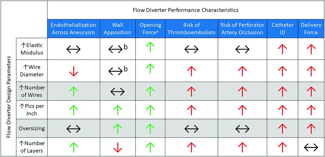
Generally, FDs are constructed by braiding a set of 36–96 wires around a mandrel and heat-treating them to lock in the shape. The mandrel is then removed, leaving a metal mesh tube that is cut to the desired length. The device may then be further processed by securing the loose wire ends, adding radiopaque markers, and/or treating the device surface. Finally, the device is loaded into its delivery system. While the general construction of FDs is simple in concept, there are many FD design parameters, including the wire diameter, the number of wires in the braid, the selection of wire material, and others, which all contribute to device performance. The selection of 1 design parameter may positively impact one FD performance characteristic while negatively impacting another. The FD engineer is tasked with selecting parameters to find a balance that optimizes the performance characteristics that the treating interventionalists find most important. The relationships between FD design parameters and effects on performance are summarized in Fig 1.

FIG 1.
  • Download figure
  • Open in new tab
  • Download powerpoint
FIG 1.

The relationship between FD design parameters and resulting performance characteristics. Green and red arrows indicate a beneficial or detrimental relationship, respectively, in terms of device performance and safety. Black horizontal arrows indicate either an independent or multifactorial relationship between the design parameters and performance characteristics. A, Improved opening force assumes that the wires within the braid do not plastically deform after being crimped in their microcatheters, allowing complete device re-expansion. B, Wall apposition is complex and depends on many variables, including the tortuosity of the parent vessel.

FD Braid Geometry

There are many FD braid geometry design parameters available for the engineer to tune. The first is the diameter of the individual wires within the braid. Increasing the wire diameter increases the overall strength of the device, improving the opening force and radial crush resistance.10,11 However, this improved opening force comes at the cost of increased delivery force and may require a larger ID microcatheter for delivery. A larger wire diameter may be associated with delayed endothelialization and the risk of thromboembolism, as is the case for much larger coronary stent struts.12 However, this relationship is yet to be extensively studied in the FD application. Market-approved FDs typically have wire diameters in the ∼18–35 µm (∼0.0007–0.001 inch) range.2

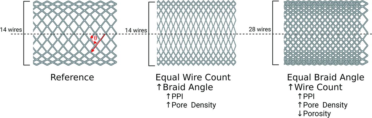
Another design parameter is the number of wires within the braid. As with the wire diameter, increasing the number of wires within the braid will increase the opening force13 of the FD at the cost of delivery force, potentially requiring a larger ID microcatheter. For example, the larger diameters of the Pipeline Vantage (Medtronic) contain 64 wires and are deployed through a 0.027-inch ID microcatheter, whereas the smaller diameters contain 48 wires and can be deployed through a 0.021-inch ID microcatheter.14 Incorporating more wires into the braid has been shown to be beneficial for promoting endothelialization across the aneurysm neck.15 However, more wires may also be associated with a greater risk of perforator artery occlusion and thromboembolism.16,17 Market-approved FDs typically contain 48–64 wires.2 A similar FD design parameter is pics-per-inch (PPI), which is defined as the number of wire crossings per inch along the length of the device. PPI can be increased by increasing the number of wires in the braid and can also be adjusted by altering the angle at which the wires are braided, as illustrated in Fig 2.11,13 When one views the FD from the longitudinal view, if the braid angle is defined as the angle between the wires and the axial axis of the stent (as defined in Fig 2), increasing the braid angle increases the PPI.11,13 A higher PPI results in FDs with increased opening force and can improve device conformity, ultimately resulting in improved wall apposition.11,13 However, the increased density of wires associated with increased PPI may also increase the delivery force and require a larger-ID microcatheter. Similar to increasing the number of wires within the braid, a higher PPI promotes aneurysm occlusion and endothelialization across the aneurysm neck but may increases the risk of perforator artery occlusion and thromboembolism.16⇓-18

FIG 2.
  • Download figure
  • Open in new tab
  • Download powerpoint
FIG 2.

Illustration of the relationship between the braid angle (defined by the red theta) and the number of wires or PPI and pore density. This figure was made with BioRender (https://www.biorender.com/).

Oversizing of FDs is another design parameter or option available to the interventionalist when selecting a device. Devices may be constructed so that their nominal diameter, resulting from the mandrel diameter around which the wires were braided, is larger than the diameter of their intended parent artery. Oversizing was initially motivated to improve wall apposition and opening force. However, in vitro fluid dynamics studies have demonstrated that oversizing causes alterations to device geometry such as the angle between the wires and pore or cell size, resulting in higher blood flow within the aneurysm sac.19 Consequently, oversizing has been correlated with lower rates of aneurysm occlusion in the clinic.20 Foreshortening of the device also needs to be considered when selecting an FD size. FDs that are overexpanded in the radial direction will end up becoming shorter. Conversely, FDs will become longer than anticipated when deployed in arteries with much smaller diameters than the device.21

Multiple layers of wire braids may also be used when constructing FDs. Increasing the number of layers theoretically increases the opening force but may require larger-ID microcatheters. The primary motivation for adding layers is to “artificially” increase the PPI and improve the flow diversion function by depositing more wires over the aneurysm neck. Multiple layers may result in increased blood stagnation within the aneurysm sac and more rapid tissue growth across the device and aneurysm neck.22 However, stacked wires increase their extension into the lumen of the parent vessel, worsening the risk of thromboembolism and the rate at which wires apposed to the artery wall become endothelialized.16,23 Furthermore, additional layers may create malapposition between the layers or more disruption of the endothelium through additional device deployments. The Flow-Redirection Endoluminal Device (FRED) (MicroVention) has a unique design with a larger wire weave on the outside, similar to that of the LVIS Stent (MicroVention), and the braided FD on the inside.2 On a related note, the use of multiple single-layer devices deployed telescopically over the aneurysm neck has also been shown to increase the rate of thromboembolic complications.24

Porosity, pore density, and the percentage of metal coverage are classic FD metrics that are ultimately a result of its selected design parameters.25 Porosity is defined as the percentage area of the device wall not covered by wires. Conversely, percentage metal coverage is defined as the percentage area of the device wall covered by wires; both are less specific because thicker wires or more wire density can result in higher-percentage metal coverage or lower porosity.25 Pore density is defined as the number of open cells or pores within the FD wall per area and is more specific.25 These characteristics will determine how well the device diverts blood flow away from the aneurysm and stagnates blood within it.26 Increasing the number of wires within the braid, PPI, and number of layers will decrease porosity and increase pore density and percentage metal coverage.11,13 Another consideration is the curvature of the parent vessel. For a given device, when deployed in a curved segment, the porosity will be greater in regions of the FD near the outer edge of the curve.21 Porosity and pore density of market-approved FDs are typically in the range of 50%–70% and 13–30 pores/mm2, respectively.27

Material Selection

The material selected to construct the wires has a notable impact on overall FD performance due to a variety of often interrelated constitutive properties. As an illustration, consider 1 material property taken in the design of FD appliances: the elastic modulus (also known as the Young modulus), which is how much the material resists elastic deformation per unit of strain or simply considered as elastic stiffness. The connection of the elastic modulus to overall device stiffness and performance is not straightforward because of other influencing factors. For example, structural stiffness depends more on wire diameter and braid parameters than the elastic modulus. Furthermore, other phenomena, such as local yielding, and elastic strain limits can dramatically change the actual device response, depending on boundary conditions.

Materials with a higher elastic modulus require a greater amount of energy to deform but will then release a greater amount of energy when springing back to their original shape (imagine a stiff spring verses a Slinky). Conversely, materials with a high elastic modulus usually show lower elastic strain limits, which can reduce size recovery, or the diameter the device is able to re-expand after being crimped into a catheter. Consequently, FDs composed of wires with a higher elastic modulus may exhibit a higher opening force or lose force before apposing because of inadequate size recovery and may require larger-ID microcatheters to compensate. Cobalt-nickel-chromium alloys have been optimized to increase the elastic modulus and, therefore, are a commonly selected FD wire material. The Pipeline Embolization Device (PED; Medtronic) and the Surpass Evolve (Stryker) are composed primarily of cobalt alloy wires.2

Another critical material property is the elastic strain limit, which is defined as how much the material can be deformed before experiencing a permanent alteration to its shape. In the FD application, a higher elastic strain limit allows devices to be crimped to smaller diameters and bent around tighter curves while still maintaining the ability to self-expand back to their original intended deployment shape. This feature is advantageous for navigating to more distal aneurysms where the parent arteries are smaller in diameter and more tortuous.28 Nickel titanium (nitinol) alloys have been optimized to increase the elastic strain limit via phase transformation and its associated superelasticity and, therefore, are also a commonly used FD wire material. FRED and p64 (phenox) are composed primarily of nitinol wires.2

While cobalt-nickel-chromium and nitinol represent excellent material selections based on their mechanical properties, they offer little radiopacity. Materials with relatively high radiodensity such as tantalum, platinum, or platinum-tungsten alloys are used to provide greater visibility than materials such as cobalt-nickel-chromium or nitinol to aid in fluoroscopy-guided delivery. All market-approved FDs feature some sort of radiopaque elements within their construction. For example, the PED and Surpass Evolve feature platinum-tungsten wires within their braid, whereas the FRED features tantalum radiopaque markers attached at either end of the device as well as unifying tantalum wires between the layers.2 Another approach to convey radiopacity is the use of drawn filled tubing (DFT) wires. DFT wires contain an inner core wire, typically composed of radiopaque platinum or tantalum, surrounded by an outer layer of nitinol or a cobalt-nickel-chromium alloy. FDs constructed from DFT wires aim to provide uniform radiopacity along the entire device length, while still taking advantage of the favorable mechanical properties of nitinol or cobalt-nickel-chromium alloys. Silk Vista Baby (Balt) and DERIVO FD (Acandis) are examples of CE-approved FDs constructed from nitinol outer/platinum inner DFT wires.2 The Pipeline Vantage is constructed from cobalt alloy outer/platinum inner DFT wires.14 Tables 1 and 2 summarize the material properties and examples of market-approved FDs constructed by the conventional FD materials.

View this table:
  • View inline
  • View popup
Table 1:

Properties of base materials used in market-approved FDs

View this table:
  • View inline
  • View popup
Table 2:

Properties of radiopaque materials used in market-approved FDs

Surface Modifications

Modifying the surface of FDs is another approach to improve device performance. The surface of the wires may be electrically, chemically, or mechanically altered or coated to produce a beneficial effect. Surface modifications aim to reduce thrombogenicity, increase endothelialization, and/or act as lubricants to reduce delivery force. Several market-approved FDs have specific surface modifications intended to improve clinical efficacy, and FD surface modifications remain a hot topic of research.

Newer iterations of the PED feature Shield Technology (Medtronic), which is a phosphorylcholine layer deposited on the wire surfaces intended to reduce thrombogenicity and increase endothelialization. In vitro studies have demonstrated reduced thrombogenicity relative to an uncoated PED.23 In vivo studies have demonstrated lower thrombogenicity and a more rapid endothelialization due to the coating.14,29 The DERIVO FD wires are treated to form surface oxides and oxynitrides, termed BlueXide, which is intended to reduce friction/delivery force and thrombogenicity.30 The newer iteration of FRED, FRED X, features a poly (2-methoxyethyl acrylate) coating, which has been shown to reduce thrombogenicity in vitro.31 A newer iteration of the p48, p48_HPC (phenox), features an antithrombogenic glycan-based hydrophilic coating that has demonstrated promising results in a 5-patient cohort of unruptured aneurysms treated with single antiplatelet therapy.32

Future Directions

As the clinical use of FDs has become more popular, the intensity with which FD technology is being researched and developed has also become more popular. The growing body of clinical FD performance data can be leveraged in the design of next-generation devices. Computational hemodynamic approaches are being applied to better understand the optimal FD design parameters for saccular blood stagnation and aneurysm occlusion.33 Active surface coatings are being engineered to impart therapeutic effects. For example, nitric oxide–releasing coatings show promise in reducing thrombogenicity and increasing endothelialization of vascular scaffolds.34 Heparin or other anticoagulant-containing coatings may also reduce thrombogenicity.35 Proteins may be attached to device surfaces to facilitate endothelial cell capture and proliferation.35 Bioresorbable FDs are also under development.27 These devices are intended to dissolve after healing the aneurysm, mitigating or eliminating complications associated with the permanent presence of conventional FDs.

CONCLUSIONS

Most practicing interventionalists gain their understanding of FD performance on the basis of their clinical experience. Choosing an FD may be related to personal preference and the availability of FDs at a given medical center. Furthermore, certain devices have only achieved market approval in specific geographic regions. For example, the PED, Surpass, and FRED are the 3 FDs currently available in the United States; Silk, p64, and DERIVO are from European companies with CE approval, and Tubridge (MicroPort) has National Medical Products Administration approval in China.2 The geographic availability influences the popularity of certain devices in certain regions. Each FD features a unique design resulting in its own set of advantages and disadvantages. A more comprehensive understanding of the relationship between engineering design principles and clinical performance may help practicing interventionalists navigate the rapidly growing FD market. Furthermore, we believe this improved understanding can promote collaboration between clinicians and engineers, ultimately accelerating the development of FD technology.

Footnotes

  • This work was partially funded by National Institutes of Health grant Nos. R01 NS076491 and R21 NS128199. Alexander Oliver is supported by American Heart Association grant No. 23PRE1012781.

  • Disclosure forms provided by the authors are available with the full text and PDF of this article at www.ajnr.org.

References

  1. 1.↵
    1. Brinjikji W,
    2. Murad MH,
    3. Lanzino G, et al
    . Endovascular treatment of intracranial aneurysms with flow diverters: a meta-analysis. Stroke 2013;44:442–47 doi:10.1161/STROKEAHA.112.678151 pmid:23321438
    Abstract/FREE Full Text
  2. 2.↵
    1. Dandapat S,
    2. Mendez-Ruiz A,
    3. Martínez-Galdámez M, et al
    . Review of current intracranial aneurysm flow diversion technology and clinical use. J Neurointerv Surg 2021;13:54–62 doi:10.1136/neurintsurg-2020-015877 pmid:32978269
    Abstract/FREE Full Text
  3. 3.↵
    1. Ravindran K,
    2. Casabella AM,
    3. Cebral J, et al
    . Mechanism of action and biology of flow diverters in the treatment of intracranial aneurysms. Neurosurgery 2020;86:S13–19 doi:10.1093/neuros/nyz324 pmid:31838528
    CrossRefPubMed
  4. 4.↵
    1. Rouchaud A,
    2. Ramana C,
    3. Brinjikji W, et al
    . Wall apposition is a key factor for aneurysm occlusion after flow diversion: a histologic evaluation in 41 rabbits. AJNR Am J Neuroradiol 2016;37:2087–91 doi:10.3174/ajnr.A4848 pmid:27390319
    Abstract/FREE Full Text
  5. 5.↵
    1. Aquarius R,
    2. de Korte A,
    3. Smits D, et al
    . The importance of wall apposition in flow diverters. Neurosurgery 2019;84:804–10 doi:10.1093/neuros/nyy092 pmid:29659995
    CrossRefPubMed
  6. 6.↵
    1. Ma J,
    2. You Z,
    3. Byrne J, et al
    . Design and mechanical properties of a novel cerebral flow diverter stent. Ann Biomed Eng 2014;42:960–70 doi:10.1007/s10439-013-0967-3 pmid:24449051
    CrossRefPubMed
  7. 7.↵
    1. Dabir D,
    2. Feisst A,
    3. Thomas D, et al
    . Physical properties of venous stents: an experimental comparison. Cardiovasc Intervent Radiol 2018;41:942–50 doi:10.1007/s00270-018-1916-1 pmid:29492633
    CrossRefPubMed
  8. 8.↵
    1. Kühn AL,
    2. Wakhloo AK,
    3. Gounis MJ, et al
    . Use of self-expanding stents for better intracranial flow diverter wall apposition. Interv Neuroradiol 2017;23:129–36 doi:10.1177/1591019916681981 pmid:27956518
    CrossRefPubMed
  9. 9.↵
    1. Kühn AL,
    2. Rodrigues KM,
    3. Wakhloo AK, et al
    . Endovascular techniques for achievement of better flow diverter wall apposition. Interv Neuroradiol 2019;25:344–47 doi:10.1177/1591019918815294 pmid:30486725
    CrossRefPubMed
  10. 10.↵
    1. Ni XY,
    2. Pan CW,
    3. Gangadhara Prusty B
    . Numerical investigations of the mechanical properties of a braided non-vascular stent design using finite element method. Comput Methods Biomech Biomed Engin 2015;18:1117–25 doi:10.1080/10255842.2013.873420 pmid:24867297
    CrossRefPubMed
  11. 11.↵
    1. Suzuki T,
    2. Takao H,
    3. Fujimura S, et al
    . Relationships between geometrical parameters and mechanical properties for a helical braided flow diverter stent. Technol Health Care 2017;25:611–23 doi:10.3233/THC-160535 pmid:28506004
    Abstract/FREE Full Text
  12. 12.↵
    1. Kastrati A,
    2. Mehilli J,
    3. Dirschinger J, et al
    . Intracoronary stenting and angiographic results: strut thickness effect on restenosis outcome (ISAR-STEREO) trial. Circulation 2001;103:2816–21 doi:10.1161/01.cir.103.23.2816 pmid:11401938
    Abstract/FREE Full Text
  13. 13.↵
    1. Kim JH,
    2. Kang TJ,
    3. Yu WR
    . Mechanical modeling of self-expandable stent fabricated using braiding technology. J Biomech 2008;41:3202–12 doi:10.1016/j.jbiomech.2008.08.005 pmid:18804764
    CrossRefPubMed
  14. 14.↵
    1. Starke RM,
    2. Thompson J,
    3. Pagani A, et al
    . Preclinical safety and efficacy evaluation of the Pipeline Vantage Embolization Device with Shield Technology. J Neurointerv Surg 2020;12:981–86 doi:10.1136/neurintsurg-2020-016043 pmid:32487767
    Abstract/FREE Full Text
  15. 15.↵
    1. Kallmes DF,
    2. Ding Y,
    3. Dai D, et al
    . A second-generation, endoluminal, flow-disrupting device for treatment of saccular aneurysms. AJNR Am J Neuroradiol 2009;30:1153–58 doi:10.3174/ajnr.A1530 pmid:19369609
    Abstract/FREE Full Text
  16. 16.↵
    1. Rogers C,
    2. Edelman ER
    . Endovascular stent design dictates experimental restenosis and thrombosis. Circulation 1995;91:2995–3001 doi:10.1161/01.cir.91.12.2995 pmid:7796511
    Abstract/FREE Full Text
  17. 17.↵
    1. Hong B,
    2. Wang K,
    3. Huang Q, et al
    . Effects of metal coverage rate of flow diversion device on neointimal growth at side branch ostium and stented artery: an animal experiment in rabbit abdominal aorta. Neuroradiology 2012;54:849–55 doi:10.1007/s00234-011-0984-6 pmid:22170078
    CrossRefPubMed
  18. 18.↵
    1. Sadasivan C,
    2. Cesar L,
    3. Seong J, et al
    . An original flow diversion device for the treatment of intracranial aneurysms: evaluation in the rabbit elastase-induced model. Stroke 2009;40:952–58 doi:10.1161/STROKEAHA.108.533760 pmid:19150864
    Abstract/FREE Full Text
  19. 19.↵
    1. Mut F,
    2. Cebral J
    . Effects of flow-diverting device oversizing on hemodynamics alteration in cerebral aneurysms. AJNR Am J Neuroradiol 2012;33:2010–16 doi:10.3174/ajnr.A3080 pmid:22555581
    Abstract/FREE Full Text
  20. 20.↵
    1. Tong X,
    2. Han M,
    3. Wu Z, et al
    . Effects of different stent size selection on Pipeline embolization device treatment of intracranial aneurysms. Ther Adv Neurol Disord 2023;16:17562864231151475 doi:10.1177/17562864231151475 pmid:36776531
    CrossRefPubMed
  21. 21.↵
    1. Shapiro M,
    2. Raz E,
    3. Becske T, et al
    . Variable porosity of the Pipeline embolization device in straight and curved vessels: a guide for optimal deployment strategy. AJNR Am J Neuroradiol 2014;35:727–33 doi:10.3174/ajnr.A3742 pmid:24072622
    Abstract/FREE Full Text
  22. 22.↵
    1. Ding Y,
    2. Tieu T,
    3. Kallmes D
    . Experimental testing of a new generation of flow diverters in sidewall aneurysms in rabbits. AJNR Am J Neuroradiol 2015;36:732–36 doi:10.3174/ajnr.A4167 pmid:25414000
    Abstract/FREE Full Text
  23. 23.↵
    1. Girdhar G,
    2. Andersen A,
    3. Pangerl E, et al
    . Thrombogenicity assessment of Pipeline Flex, Pipeline Shield, and FRED flow diverters in an in vitro human blood physiological flow loop model. J Biomedical Materials Res 2018;106:3195–202 doi:10.1002/jbm.a.36514
    CrossRef
  24. 24.↵
    1. Tan LA,
    2. Keigher KM,
    3. Munich SA, et al
    . Thromboembolic complications with Pipeline Embolization Device placement: impact of procedure time, number of stents and pre-procedure P2Y12 reaction unit (PRU) value. J Neurointerv Surg 2015;7:217–21 doi:10.1136/neurintsurg-2014-011111 pmid:24553344
    Abstract/FREE Full Text
  25. 25.↵
    1. Lieber BB,
    2. Sadasivan C
    . Endoluminal scaffolds for vascular reconstruction and exclusion of aneurysms from the cerebral circulation. Stroke 2010;41:S21–25 doi:10.1161/STROKEAHA.110.595066 pmid:20876497
    Abstract/FREE Full Text
  26. 26.↵
    1. Dholakia R,
    2. Sadasivan C,
    3. Fiorella DJ, et al
    . Hemodynamics of flow diverters. J Biomech Eng 2017;139 doi:10.1115/1.4034932 pmid:27727400
    CrossRefPubMed
  27. 27.↵
    1. Oliver AA,
    2. Carlson KD,
    3. Bilgin C, et al
    . Bioresorbable flow diverters for the treatment of intracranial aneurysms: review of current literature and future directions. J Neurointerv Surg 2023;15:178–82 doi:10.1136/neurintsurg-2022-018941 pmid:35636949
    Abstract/FREE Full Text
  28. 28.↵
    1. Chiu AH,
    2. Phillips TJ
    . Future directions of flow diverter therapy. Neurosurgery 2020;86:S106–16 doi:10.1093/neuros/nyz343 pmid:31838531
    CrossRefPubMed
  29. 29.↵
    1. Matsuda Y,
    2. Jang DK,
    3. Chung J, et al
    . Preliminary outcomes of single antiplatelet therapy for surface-modified flow diverters in an animal model: analysis of neointimal development and thrombus formation using OCT. J Neurointerv Surg 2019;11:74–77 doi:10.1136/neurintsurg-2018-013935 pmid:29804090
    Abstract/FREE Full Text
  30. 30.↵
    1. Akgul E,
    2. Onan HB,
    3. Akpinar S, et al
    . The DERIVO embolization device in the treatment of intracranial aneurysms: short-and midterm results. World Neurosurg 2016;95:229–40 doi:10.1016/j.wneu.2016.07.101 pmid:27514698
    CrossRefPubMed
  31. 31.↵
    1. Yoshizawa K,
    2. Kobayashi H,
    3. Kaneki A, et al
    . Poly (2-methoxyethyl acrylate) (PMEA) improves the thromboresistance of FRED flow diverters: a thrombogenic evaluation of flow diverters with human blood under flow conditions. J Neurointerv Surg 2023;15:1001–06 doi:10.1136/jnis-2022-019248 pmid:36180206
    Abstract/FREE Full Text
  32. 32.↵
    1. Bhogal P,
    2. Bleise C,
    3. Chudyk J, et al
    . The p48_HPC antithrombogenic flow diverter: initial human experience using single antiplatelet therapy. J Int Med Res 2020;48:300060519879580 doi:10.1177/0300060519879580 pmid:31612765
    CrossRefPubMed
  33. 33.↵
    1. Xu L,
    2. Zhao B,
    3. Liu X, et al
    . Computational methods applied to analyze the hemodynamic effects of flow-diverter devices in the treatment of cerebral aneurysms: current status and future directions. Med Nov Technol Devices 2019;3:100018 doi:10.1016/j.medntd.2019.100018
    CrossRef
  34. 34.↵
    1. Rao J,
    2. Pan Bei H,
    3. Yang Y, et al
    . Nitric oxide-producing cardiovascular stent coatings for prevention of thrombosis and restenosis. Front Bioeng Biotechnol 2020;8:578 doi:10.3389/fbioe.2020.00578 pmid:32671029
    CrossRefPubMed
  35. 35.↵
    1. Liu P,
    2. Liu Y,
    3. Li P, et al
    . Rosuvastatin-and heparin-loaded poly (l-lactide-co-caprolactone) nanofiber aneurysm stent promotes endothelialization via vascular endothelial growth factor type A modulation. ACS Appl Mater Interfaces 2018;10:41012–18 doi:10.1021/acsami.8b11714 pmid:30403126
    CrossRefPubMed
  36. 36.
    1. Bhogal P,
    2. Moreno RM,
    3. Ganslandt O, et al
    . Use of flow diverters in the treatment of unruptured saccular aneurysms of the anterior cerebral artery. J Neurointerv Surg 2017;9:283–89 doi:10.1136/neurintsurg-2016-012648 pmid:27789789
    Abstract/FREE Full Text
  • Received August 8, 2023.
  • Accepted after revision October 29, 2023.
  • © 2024 by American Journal of Neuroradiology
PreviousNext
Back to top

In this issue

American Journal of Neuroradiology: 45 (4)
American Journal of Neuroradiology
Vol. 45, Issue 4
1 Apr 2024
  • Table of Contents
  • Index by author
  • Complete Issue (PDF)
Advertisement
Print
Download PDF
Email Article

Thank you for your interest in spreading the word on American Journal of Neuroradiology.

NOTE: We only request your email address so that the person you are recommending the page to knows that you wanted them to see it, and that it is not junk mail. We do not capture any email address.

Enter multiple addresses on separate lines or separate them with commas.
Intraluminal Flow Diverter Design Primer for Neurointerventionalists
(Your Name) has sent you a message from American Journal of Neuroradiology
(Your Name) thought you would like to see the American Journal of Neuroradiology web site.
CAPTCHA
This question is for testing whether or not you are a human visitor and to prevent automated spam submissions.
Cite this article
Alexander A. Oliver, Yigit Can Senol, Cem Bilgin, Jeremy E. Schaffer, Ramanathan Kadirvel, David F. Kallmes, John M. Wainwright
Intraluminal Flow Diverter Design Primer for Neurointerventionalists
American Journal of Neuroradiology Apr 2024, 45 (4) 365-370; DOI: 10.3174/ajnr.A8076

Citation Manager Formats

  • BibTeX
  • Bookends
  • EasyBib
  • EndNote (tagged)
  • EndNote 8 (xml)
  • Medlars
  • Mendeley
  • Papers
  • RefWorks Tagged
  • Ref Manager
  • RIS
  • Zotero
0 Responses
Respond to this article
Share
Bookmark this article
Intraluminal Flow Diverter Design for NeuroIR
Alexander A. Oliver, Yigit Can Senol, Cem Bilgin, Jeremy E. Schaffer, Ramanathan Kadirvel, David F. Kallmes, John M. Wainwright
American Journal of Neuroradiology Apr 2024, 45 (4) 365-370; DOI: 10.3174/ajnr.A8076
del.icio.us logo Twitter logo Facebook logo Mendeley logo
  • Tweet Widget
  • Facebook Like
  • Google Plus One
Purchase

Jump to section

  • Article
    • Abstract
    • ABBREVIATIONS:
    • CONCLUSIONS
    • Footnotes
    • References
  • Figures & Data
  • Info & Metrics
  • Responses
  • References
  • PDF

Related Articles

  • No related articles found.
  • PubMed
  • Google Scholar

Cited By...

  • Braids and beyond: a comprehensive study on pipeline device braid stability from PREMIER data
  • Flow diverter braid deformation following treatment of cerebral aneurysms: incidence, clinical relevance, and potential risk factors
  • Crossref (8)
  • Google Scholar

This article has been cited by the following articles in journals that are participating in Crossref Cited-by Linking.

  • Flow Diversion for Endovascular Treatment of Intracranial Aneurysms: Past, Present, and Future Directions
    Michael Gaub, Greg Murtha, Molly Lafuente, Matthew Webb, Anqi Luo, Lee A. Birnbaum, Justin R. Mascitelli, Fadi Al Saiegh
    Journal of Clinical Medicine 2024 13 14
  • Flow diverter braid deformation following treatment of cerebral aneurysms: incidence, clinical relevance, and potential risk factors
    Dan Adrian Popica, Jonathan Cortese, Alexander A Oliver, Vincent Plaforet, Ignacio Molina Diaz, Fernanda Rodriguez-Erazú, Léon Ikka, Cristian Mihalea, Vanessa Chalumeau, David F Kallmes, Jildaz Caroff, Laurent Spelle
    Journal of NeuroInterventional Surgery 2024
  • Braids and beyond: a comprehensive study on pipeline device braid stability from PREMIER data
    Fernanda Rodriguez-Erazú, Gustavo M Cortez, Demetrius K Lopes, Salvador F Gutierrez-Aguirre, Otavio Frederico De Toledo, Amin Aghaebrahim, Eric Sauvageau, David F Kallmes, Jens Fiehler, Ricardo A Hanel
    Journal of NeuroInterventional Surgery 2024
  • Evaluation of FeMnN alloy bioresorbable flow diverters in the rabbit elastase induced aneurysm model
    Alexander A. Oliver, Cem Bilgin, Jonathan Cortese, Esref A. Bayraktar, Daying Dai, Yong Hong Ding, Kent D. Carlson, Adam J. Griebel, Jeremy E. Schaffer, Mitchell L. Connon, Dan Dragomir-Daescu, Ramanathan Kadirvel, Roger J. Guillory, David F. Kallmes
    Frontiers in Bioengineering and Biotechnology 2025 13
  • Advancing flow diverter porosity assessment: what can it tell us about occlusion rates?
    Santiago Estevez-Areco, Laura Obradó, Romina Muñoz, Ignacio Larrabide
    Expert Review of Medical Devices 2025 22 3
  • Evaluation of FeMnN alloy bioresorbable flow diverting stents in the rabbit abdominal aorta
    Alexander A. Oliver, Cem Bilgin, Mitchell L. Connon, Andrew J. Vercnocke, Esref A. Bayraktar, Jonathan Cortese, Daying Dai, Yong Hong Ding, Sarah A. Erdahl, John Pederson, Kent D. Carlson, Adam J. Griebel, Jeremy E. Schaffer, Dan Dragomir-Daescu, Ramanathan Kadirvel, Roger J. Guillory, David F. Kallmes
    Bioactive Materials 2025 48
  • Magnetizable flow diverters can magnetically capture and retain endothelial cells to promote healing in rabbit arteries
    Alexander A. Oliver, Julien Ognard, Jonathan Cortese, Esref A. Bayraktar, Aleksandra M. Zielonka, David F. Kallmes, Brandon J. Tefft, Ramanathan Kadirvel
    Journal of Neuroradiology 2025 52 4
  • Radiopaque FeMnN-Mo composite drawn filled tubing wires for braided absorbable neurovascular devices
    Adam J. Griebel, Petra Maier, Henry Summers, Benjamin Clausius, Isabella Kanasty, Weilue He, Nicholas Peterson, Carolyn Czerniak, Alexander A. Oliver, David F. Kallmes, Ramanathan Kadirvel, Jeremy E. Schaffer, Roger J. Guillory
    Bioactive Materials 2024 40

More in this TOC Section

  • Flow diversion for distal circulation aneurysms
  • Neuroform Atlas Stent for Intracranial Aneurysms
  • Transophthalmic Artery Embolization of Meningiomas
Show more Neurointervention

Similar Articles

Advertisement

Indexed Content

  • Current Issue
  • Accepted Manuscripts
  • Article Preview
  • Past Issues
  • Editorials
  • Editor's Choice
  • Fellows' Journal Club
  • Letters to the Editor
  • Video Articles

Cases

  • Case Collection
  • Archive - Case of the Week
  • Archive - Case of the Month
  • Archive - Classic Case

More from AJNR

  • Trainee Corner
  • Imaging Protocols
  • MRI Safety Corner
  • Book Reviews

Multimedia

  • AJNR Podcasts
  • AJNR Scantastics

Resources

  • Turnaround Time
  • Submit a Manuscript
  • Submit a Video Article
  • Submit an eLetter to the Editor/Response
  • Manuscript Submission Guidelines
  • Statistical Tips
  • Fast Publishing of Accepted Manuscripts
  • Graphical Abstract Preparation
  • Imaging Protocol Submission
  • Evidence-Based Medicine Level Guide
  • Publishing Checklists
  • Author Policies
  • Become a Reviewer/Academy of Reviewers
  • News and Updates

About Us

  • About AJNR
  • Editorial Board
  • Editorial Board Alumni
  • Alerts
  • Permissions
  • Not an AJNR Subscriber? Join Now
  • Advertise with Us
  • Librarian Resources
  • Feedback
  • Terms and Conditions
  • AJNR Editorial Board Alumni

American Society of Neuroradiology

  • Not an ASNR Member? Join Now

© 2025 by the American Society of Neuroradiology All rights, including for text and data mining, AI training, and similar technologies, are reserved.
Print ISSN: 0195-6108 Online ISSN: 1936-959X

Powered by HighWire