Advertisement

Main menu

  • Home
  • Content
    • Current Issue
    • Accepted Manuscripts
    • Article Preview
    • Past Issue Archive
    • Video Articles
    • AJNR Case Collection
    • Case of the Week Archive
    • Case of the Month Archive
    • Classic Case Archive
  • Special Collections
    • AJNR Awards
    • Low-Field MRI
    • Alzheimer Disease
    • ASNR Foundation Special Collection
    • Photon-Counting CT
    • View All
  • Multimedia
    • AJNR Podcasts
    • AJNR SCANtastic
    • Trainee Corner
    • MRI Safety Corner
    • Imaging Protocols
  • For Authors
    • Submit a Manuscript
    • Submit a Video Article
    • Submit an eLetter to the Editor/Response
    • Manuscript Submission Guidelines
    • Statistical Tips
    • Fast Publishing of Accepted Manuscripts
    • Graphical Abstract Preparation
    • Imaging Protocol Submission
    • Author Policies
  • About Us
    • About AJNR
    • Editorial Board
    • Editorial Board Alumni
  • More
    • Become a Reviewer/Academy of Reviewers
    • Subscribers
    • Permissions
    • Alerts
    • Feedback
    • Advertisers
    • ASNR Home

User menu

  • Alerts
  • Log in

Search

  • Advanced search
American Journal of Neuroradiology

American Journal of Neuroradiology

ASHNR American Society of Functional Neuroradiology ASHNR American Society of Pediatric Neuroradiology ASSR
  • Alerts
  • Log in

Advanced Search

  • Home
  • Content
    • Current Issue
    • Accepted Manuscripts
    • Article Preview
    • Past Issue Archive
    • Video Articles
    • AJNR Case Collection
    • Case of the Week Archive
    • Case of the Month Archive
    • Classic Case Archive
  • Special Collections
    • AJNR Awards
    • Low-Field MRI
    • Alzheimer Disease
    • ASNR Foundation Special Collection
    • Photon-Counting CT
    • View All
  • Multimedia
    • AJNR Podcasts
    • AJNR SCANtastic
    • Trainee Corner
    • MRI Safety Corner
    • Imaging Protocols
  • For Authors
    • Submit a Manuscript
    • Submit a Video Article
    • Submit an eLetter to the Editor/Response
    • Manuscript Submission Guidelines
    • Statistical Tips
    • Fast Publishing of Accepted Manuscripts
    • Graphical Abstract Preparation
    • Imaging Protocol Submission
    • Author Policies
  • About Us
    • About AJNR
    • Editorial Board
    • Editorial Board Alumni
  • More
    • Become a Reviewer/Academy of Reviewers
    • Subscribers
    • Permissions
    • Alerts
    • Feedback
    • Advertisers
    • ASNR Home
  • Follow AJNR on Twitter
  • Visit AJNR on Facebook
  • Follow AJNR on Instagram
  • Join AJNR on LinkedIn
  • RSS Feeds

AJNR Awards, New Junior Editors, and more. Read the latest AJNR updates

OtherSpine Imaging and Spine Image-Guided Interventions

CT Evaluation of Lumbar Interbody Fusion: Current Concepts

Alan L. Williams, Matthew F. Gornet and J. Kenneth Burkus
American Journal of Neuroradiology September 2005, 26 (8) 2057-2066;
Alan L. Williams
  • Find this author on Google Scholar
  • Find this author on PubMed
  • Search for this author on this site
Matthew F. Gornet
  • Find this author on Google Scholar
  • Find this author on PubMed
  • Search for this author on this site
J. Kenneth Burkus
  • Find this author on Google Scholar
  • Find this author on PubMed
  • Search for this author on this site
  • Article
  • Figures & Data
  • Info & Metrics
  • Responses
  • References
  • PDF
Loading

Article Figures & Data

Figures

  • Tables
  • Fig 1.
    • Download figure
    • Open in new tab
    • Download powerpoint
    Fig 1.

    A, BAK cage (Zimmer Spine). B, Ray Threaded Fusion Cage (Stryker Spine). C, LT-CAGE. D, INTER FIX device (panels C and D; Medtronic Sofamor Danek). E, Harms cage (DePuy Spine). F, PEEK cage (Medtronic Sofamor Danek). G, JAGUAR I/F CAGE (Brantigan Device; DePuy Spine). H, BOOMERANG. I, Bone Dowel. J, Femoral Ring (panels H–J courtesy of Medtronic Sofamor Danek).

  • Fig 2.
    • Download figure
    • Open in new tab
    • Download powerpoint
    Fig 2.

    Normal progression of interbody fusion in a 28-year-old woman. A, On a coronal reformatted CT image, obtained 6 months after surgery, new bone formation is evident within (black arrow) and adjacent to (white arrow) the LT-CAGE devices. B, Ten months after surgery, reformatted CT image shows additional new bone formation, especially lateral to the fusion devices (white arrows), with bony bridging across the disk space.

  • Fig 3.
    • Download figure
    • Open in new tab
    • Download powerpoint
    Fig 3.

    Subsidence of LT-CAGE devices at L5–S1. Sagittal (A) and coronal (B) reformatted CT images demonstrate subsidence of the LT fusion devices (small arrows) through the L5 inferior endplate into the vertebral body in a 60-year-old man. The sagittal image demonstrates new bone formation (large arrow) posterior to the fusion device with bony bridging taking place across the disk space.

  • Fig 4.
    • Download figure
    • Open in new tab
    • Download powerpoint
    Fig 4.

    Lucency at fusion device margins. Coronal (A) and sagittal (B) reformatted images at L5–S1 in a 45-year-old man demonstrate lucency (arrows) at the margins of both LT CAGEs, suggesting delayed or failed fusion.
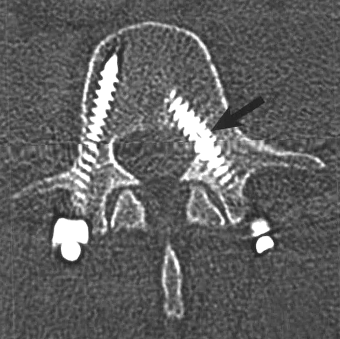
  • Fig 5.
    • Download figure
    • Open in new tab
    • Download powerpoint
    Fig 5.

    Lucency surrounding pedicle screws. Coronal reformatted image at L5–S1 in a 58-year-old woman demonstrates lucency (large white arrows) surrounding the pedicle screws at S1 and subtle lucency around the L5 screws (small white arrows), signifying instrumentation loosening and fusion failure. Note the fusion devices (black arrows) within the disk space.
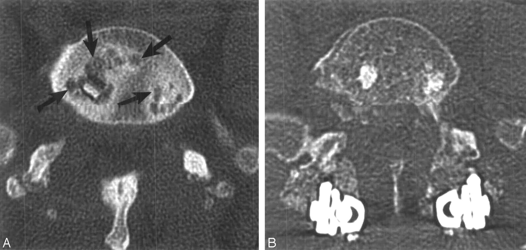
  • Fig 6.
    • Download figure
    • Open in new tab
    • Download powerpoint
    Fig 6.

    Cystic changes within the endplates adjacent to the implants. A, Five months after surgery in a 62-year-old woman, CT scan shows cystic changes (arrows) in the endplates at the L5–S1 level on an axial image. B, Twenty-one months after the application of posterior instrumentation, CT scan shows that the cystic changes are much less prominent as the fusion is progressing to solid bony union.

  • Fig 7.
    • Download figure
    • Open in new tab
    • Download powerpoint
    Fig 7.

    Broken pedicle screw. CT scan shows the fractured right S1 pedicle screw (white arrow). A Bone Dowel (black arrow) is present in the L5–S1 disk space.

  • Fig 8.
    • Download figure
    • Open in new tab
    • Download powerpoint
    Fig 8.

    Medial orientation of pedicle screw. In a 48-year-old man, an axial image demonstrates that the left L4 pedicle screw (arrow) has penetrated the medial cortex of the pedicle in the vicinity of the L4 nerve root.

  • Fig 9.
    • Download figure
    • Open in new tab
    • Download powerpoint
    Fig 9.

    Linear lucency parallel to the endplate in new bone formation in a 31-year-old woman. Coronal (A) and sagittal (B) reformatted images at L5–S1 demonstrate irregular linear lucency (arrows) through new bone formation within the disk space, indicating failed fusion.

  • Fig 10.
    • Download figure
    • Open in new tab
    • Download powerpoint
    Fig 10.

    Dislodged fusion device. In a 51-year-old woman, axial (A) and coronal (B) reformatted images at L5–S1 demonstrate the left-sided mesh titanium fusion device (straight white arrow) displaced laterally within and lateral to the intervertebral foramen in the vicinity of the left L5 dorsal root ganglion and nerve. A Bone Dowel (curved white arrow) is noted in the midline in the disk space. Bony bridging (arrowheads) across the disk space is evident.

  • Fig 11.
    • Download figure
    • Open in new tab
    • Download powerpoint
    Fig 11.

    Intervertebral disk prosthesis. Lateral scout view (A) demonstrates a Maverick-type chrome cobalt disk prosthesis (Medtronic Sofamor Danek) within the L4–5 intervertebral disk space in a 33-year-old woman. Coronal (B) and sagittal (C) reformatted images demonstrate artifact related to the device, degrading anatomic detail at this level.

Tables

  • Figures
  • Suggested CT scanning protocol*

    Patient orientationSupine, feet first
    Gantry tilt0°
    Region of interestInitial exam: mid-T12 to mid-sacrum
    Subsequent exams: One level above to one level below fusion level(s)
    Kernel/algorithmB80/bone
    Milliamperage (mA)250
    Kilovoltage (kV)140
    Field of view (FOV)14 cm
    Matrix512 × 512
    Volume acquisition slice collimation1.0 mm
    Image reconstruction progression
        Step 1Reconstructed axial 3.0-mm-thick sections; entire scan volume
        Step 2Reconstructed axial 1.0-mm-thick sections at 0.5-mm increments (overlapped); region of interest only
        Step 3Reformatted images in 3 planes; region of interest; 1.0 mm axial (parallel to the disc); 3.0 mm coronal and sagittal
        Window and level settings2000–3000/350–400
    • * Multisection (4) CT scanner.

PreviousNext
Back to top

In this issue

American Journal of Neuroradiology: 26 (8)
American Journal of Neuroradiology
Vol. 26, Issue 8
1 Sep 2005
  • Table of Contents
  • Index by author
Advertisement
Print
Download PDF
Email Article

Thank you for your interest in spreading the word on American Journal of Neuroradiology.

NOTE: We only request your email address so that the person you are recommending the page to knows that you wanted them to see it, and that it is not junk mail. We do not capture any email address.

Enter multiple addresses on separate lines or separate them with commas.
CT Evaluation of Lumbar Interbody Fusion: Current Concepts
(Your Name) has sent you a message from American Journal of Neuroradiology
(Your Name) thought you would like to see the American Journal of Neuroradiology web site.
CAPTCHA
This question is for testing whether or not you are a human visitor and to prevent automated spam submissions.
Cite this article
Alan L. Williams, Matthew F. Gornet, J. Kenneth Burkus
CT Evaluation of Lumbar Interbody Fusion: Current Concepts
American Journal of Neuroradiology Sep 2005, 26 (8) 2057-2066;

Citation Manager Formats

  • BibTeX
  • Bookends
  • EasyBib
  • EndNote (tagged)
  • EndNote 8 (xml)
  • Medlars
  • Mendeley
  • Papers
  • RefWorks Tagged
  • Ref Manager
  • RIS
  • Zotero
0 Responses
Respond to this article
Share
Bookmark this article
CT Evaluation of Lumbar Interbody Fusion: Current Concepts
Alan L. Williams, Matthew F. Gornet, J. Kenneth Burkus
American Journal of Neuroradiology Sep 2005, 26 (8) 2057-2066;
del.icio.us logo Twitter logo Facebook logo Mendeley logo
  • Tweet Widget
  • Facebook Like
  • Google Plus One

Jump to section

  • Article
    • Interbody Fusion Techniques
    • Common Lumbar Interbody Fusion Devices
    • Metal Devices
    • Composite Devices
    • Biologic Devices
    • Bone Graft Substitutes
    • Radiographic Evaluation Of Interbody Fusion
    • MR Imaging
    • CT
    • CT Protocol
    • CT Interpretation
    • CT Features of Delayed or Failed Fusion
    • Future Advances
    • Conclusion
    • Acknowledgments
    • References
  • Figures & Data
  • Info & Metrics
  • Responses
  • References
  • PDF

Related Articles

  • No related articles found.
  • PubMed
  • Google Scholar

Cited By...

  • Cost-Effectiveness and Clinical Outcomes of Lateral Lumbar Interbody Fusion With Tricalcium Phosphate and Iliac Bone Graft Compared With Posterior Lumbar Interbody Fusion With Local Bone Graft in Single-Level Lumbar Spinal Fusion Surgery in Thailand
  • Expandable Lateral Lumbar Cages With Integrated Fixation: A Viable Option for Rostral Adjacent Segment Disease
  • Predictive Factors and Rates of Fusion in Minimally Invasive Transforaminal Lumbar Interbody Fusion Utilizing rhBMP-2 or Mesenchymal Stem Cells
  • Transforaminal Lumbar Interbody Fusion With Viable Allograft: 75 Consecutive Cases at 12-Month Follow-up
  • Fusion after minimally disruptive anterior lumbar interbody fusion: Analysis of extreme lateral interbody fusion by computed tomography
  • The Use of Bone Morphogenetic Protein in Lumbar Spine Surgery
  • Significance of Early CT Evaluation after Lumbar Interbody Fusions Using Recombinant Human Bone Morphogenetic Protein-2
  • Low Back Pain
  • Crossref
  • Google Scholar

This article has not yet been cited by articles in journals that are participating in Crossref Cited-by Linking.

More in this TOC Section

  • Management Outcomes For VO Spine Biopsy
  • Cone Beam CT Myelography
  • Post-Procedural Brachial Neuritis Features
Show more SPINE IMAGING AND SPINE IMAGE-GUIDED INTERVENTIONS

Similar Articles

Advertisement

Indexed Content

  • Current Issue
  • Accepted Manuscripts
  • Article Preview
  • Past Issues
  • Editorials
  • Editor's Choice
  • Fellows' Journal Club
  • Letters to the Editor
  • Video Articles

Cases

  • Case Collection
  • Archive - Case of the Week
  • Archive - Case of the Month
  • Archive - Classic Case

More from AJNR

  • Trainee Corner
  • Imaging Protocols
  • MRI Safety Corner
  • Book Reviews

Multimedia

  • AJNR Podcasts
  • AJNR Scantastics

Resources

  • Turnaround Time
  • Submit a Manuscript
  • Submit a Video Article
  • Submit an eLetter to the Editor/Response
  • Manuscript Submission Guidelines
  • Statistical Tips
  • Fast Publishing of Accepted Manuscripts
  • Graphical Abstract Preparation
  • Imaging Protocol Submission
  • Evidence-Based Medicine Level Guide
  • Publishing Checklists
  • Author Policies
  • Become a Reviewer/Academy of Reviewers
  • News and Updates

About Us

  • About AJNR
  • Editorial Board
  • Editorial Board Alumni
  • Alerts
  • Permissions
  • Not an AJNR Subscriber? Join Now
  • Advertise with Us
  • Librarian Resources
  • Feedback
  • Terms and Conditions
  • AJNR Editorial Board Alumni

American Society of Neuroradiology

  • Not an ASNR Member? Join Now

© 2025 by the American Society of Neuroradiology All rights, including for text and data mining, AI training, and similar technologies, are reserved.
Print ISSN: 0195-6108 Online ISSN: 1936-959X

Powered by HighWire