Advertisement

Main menu

  • Home
  • Content
    • Current Issue
    • Accepted Manuscripts
    • Article Preview
    • Past Issue Archive
    • Video Articles
    • AJNR Case Collection
    • Case of the Week Archive
    • Case of the Month Archive
    • Classic Case Archive
  • Special Collections
    • AJNR Awards
    • Low-Field MRI
    • Alzheimer Disease
    • ASNR Foundation Special Collection
    • Photon-Counting CT
    • View All
  • Multimedia
    • AJNR Podcasts
    • AJNR SCANtastic
    • Trainee Corner
    • MRI Safety Corner
    • Imaging Protocols
  • For Authors
    • Submit a Manuscript
    • Submit a Video Article
    • Submit an eLetter to the Editor/Response
    • Manuscript Submission Guidelines
    • Statistical Tips
    • Fast Publishing of Accepted Manuscripts
    • Graphical Abstract Preparation
    • Imaging Protocol Submission
    • Author Policies
  • About Us
    • About AJNR
    • Editorial Board
    • Editorial Board Alumni
  • More
    • Become a Reviewer/Academy of Reviewers
    • Subscribers
    • Permissions
    • Alerts
    • Feedback
    • Advertisers
    • ASNR Home

User menu

  • Alerts
  • Log in

Search

  • Advanced search
American Journal of Neuroradiology

American Journal of Neuroradiology

ASHNR American Society of Functional Neuroradiology ASHNR American Society of Pediatric Neuroradiology ASSR
  • Alerts
  • Log in

Advanced Search

  • Home
  • Content
    • Current Issue
    • Accepted Manuscripts
    • Article Preview
    • Past Issue Archive
    • Video Articles
    • AJNR Case Collection
    • Case of the Week Archive
    • Case of the Month Archive
    • Classic Case Archive
  • Special Collections
    • AJNR Awards
    • Low-Field MRI
    • Alzheimer Disease
    • ASNR Foundation Special Collection
    • Photon-Counting CT
    • View All
  • Multimedia
    • AJNR Podcasts
    • AJNR SCANtastic
    • Trainee Corner
    • MRI Safety Corner
    • Imaging Protocols
  • For Authors
    • Submit a Manuscript
    • Submit a Video Article
    • Submit an eLetter to the Editor/Response
    • Manuscript Submission Guidelines
    • Statistical Tips
    • Fast Publishing of Accepted Manuscripts
    • Graphical Abstract Preparation
    • Imaging Protocol Submission
    • Author Policies
  • About Us
    • About AJNR
    • Editorial Board
    • Editorial Board Alumni
  • More
    • Become a Reviewer/Academy of Reviewers
    • Subscribers
    • Permissions
    • Alerts
    • Feedback
    • Advertisers
    • ASNR Home
  • Follow AJNR on Twitter
  • Visit AJNR on Facebook
  • Follow AJNR on Instagram
  • Join AJNR on LinkedIn
  • RSS Feeds

AJNR Awards, New Junior Editors, and more. Read the latest AJNR updates

OtherSpine Imaging and Spine Image-Guided Interventions

Percutaneous Vertebroplasty: Complication Avoidance and Technique Optimization

John M. Mathis
American Journal of Neuroradiology September 2003, 24 (8) 1697-1706;
John M. Mathis
  • Find this author on Google Scholar
  • Find this author on PubMed
  • Search for this author on this site
  • Article
  • Figures & Data
  • Info & Metrics
  • Responses
  • References
  • PDF
Loading

Article Figures & Data

Figures

  • Tables
  • Fig 1.
    • Download figure
    • Open in new tab
    • Download powerpoint
    Fig 1.

    A, Lateral radiograph during vertebroplasty showing cement extending to the posterior vertebral margin (black arrow).

    B, Post-PV CT scan demonstrates a small leak into the epidural venous plexus (black arrow). This leak was asymptomatic.
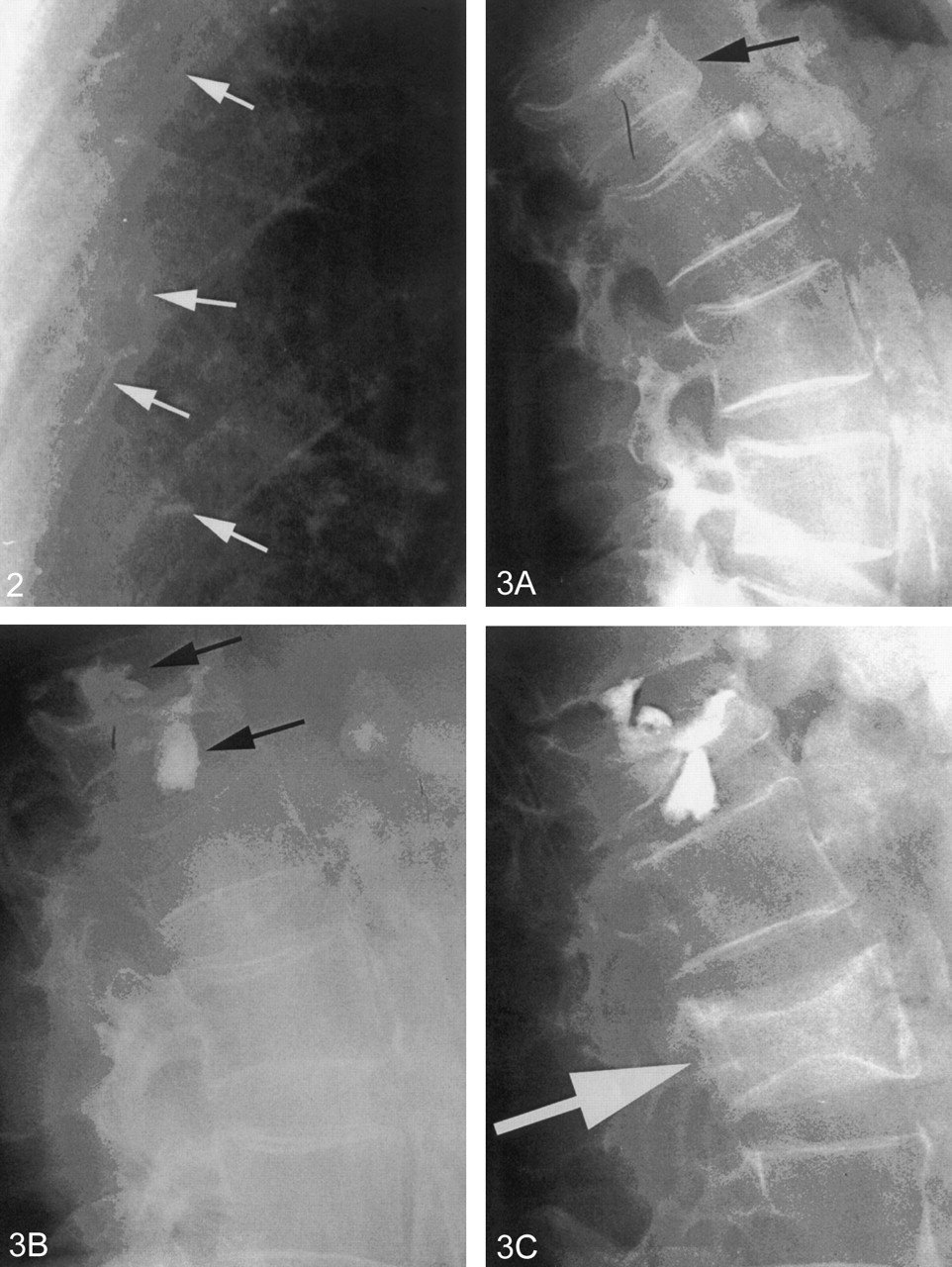
  • Fig 2.
    • Download figure
    • Open in new tab
    • Download powerpoint
    Fig 2.

    Portion of a chest radiograph after PV showing small radiopaque cement emboli (white arrows) in peripheral pulmonary vessels. This patient had no pulmonary symptoms.

  • Fig 3.
    • Download figure
    • Open in new tab
    • Download powerpoint
    Fig 3.

    A, Lateral radiograph of the spine showing a moderately compressed vertebra (black arrow).

    B, Postvertebroplasty, there are large leaks of cement (black arrows) into the adjacent disk spaces.

    C, Six months later, the patient returned with a second fracture (white arrow). This fracture is not an adjacent level. Adjacent levels did not fracture despite the large disk leaks.

  • Fig 4.
    • Download figure
    • Open in new tab
    • Download powerpoint
    Fig 4.

    A, Postvertebroplasty CT scan demonstrates large cement leaks into the spinal canal, neural foramin (black arrow), and perispinus region. This patient had paresis and radiculopathy.

    B, Postkyphoplasty CT scan shows large leaks into the spinal canal (black arrows), which created paraplegia.
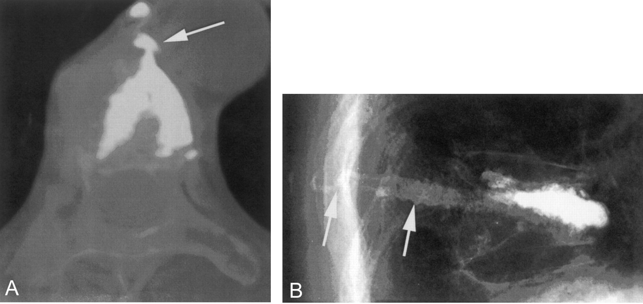
  • Fig 5.
    • Download figure
    • Open in new tab
    • Download powerpoint
    Fig 5.

    A, Postkyphoplasty CT scan. The lateral wall was disrupted by the balloon inflation, and a large cement leak into the mediastinum resulted (white arrow). For weeks following the procedure, this patient had severe, persistent pain.

    B, Lateral radiography after vertebroplasty with a slow-set PMMA. The needles were withdrawn and the cement was still liquid enough to flow into the needle tracts and into the soft tissue (white arrows). This created local discomfort to pressure.
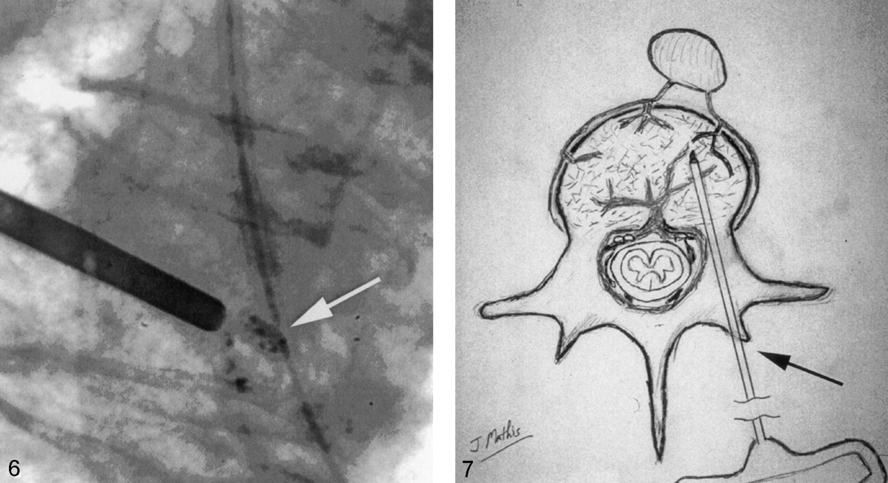
  • Fig 6.
    • Download figure
    • Open in new tab
    • Download powerpoint
    Fig 6.

    Radiograph showing appropriately opacified cement (white arrow) that can be easily seen even in very small quantities.

  • Fig 7.
    • Download figure
    • Open in new tab
    • Download powerpoint
    Fig 7.

    Drawing depicting the needle entry site into the bone (black arrow) for a transpedicular approach. Following removal of the needle, local pressure allows one to easily achieve hemostasis in this situation.

  • Fig 8.
    • Download figure
    • Open in new tab
    • Download powerpoint
    Fig 8.

    A, T2 sagittal MR imaging demonstrating a high signal intensity collection (black arrow) below the superior endplate of this compressed vertebra. This represents a fluid-filled vertebral cleft.

    B, Lateral radiograph showing an air-filled cleft (black arrow) in a compression fracture.

  • Fig 9.
    • Download figure
    • Open in new tab
    • Download powerpoint
    Fig 9.

    A, Lateral radiograph showing early cement filling of a cleft below the superior endplate (black arrow) of a compressed vertebra. Note that the needle tips are separated from the cleft and the cleft is filling preferentially.

    B, Anterioposterior view of the same vertebra at completion of the vertebroplasty. The cleft (black arrow) has been completely filled with cement. Relatively little cement has been deposited into the rest of the vertebra. This typically results in good pain relief without the need for repeat filling of the noncleft portion of the vertebra.

  • Fig 10.
    • Download figure
    • Open in new tab
    • Download powerpoint
    Fig 10.

    A, Lateral radiograph demonstrating marked compression of a lower thoracic vertebra. Note the 18° of kyphosis before vertebroplasty.

    B, With mild extension of the body, some height was restored to vertebra during vertebroplasty. This postvertebroplasty image shows that the kyphosis has been reduced to 9°.

  • Fig 11.
    • Download figure
    • Open in new tab
    • Download powerpoint
    Fig 11.

    A, Lateral radiograph during vertebroplasty of a compression fracture due to breast carcinoma. Note that the thecal sac was first opacified with myelographic contrast. This allows one to watch for deformation of the thecal sac that would indicate tumor displacement during cement introduction.

    B, With the thecal sac opacified, axial CT scans provide the most sensitive method to monitor PV for thecal sac compression created by tumor displaced during cement injection.

  • Fig 12.
    • Download figure
    • Open in new tab
    • Download powerpoint
    Fig 12.

    A, Sagittal T1 MR imaging (midline) showing complete central compression of T11.

    B, Sagittal T1 MR imaging (lateral vertebral margin) reveals considerable residual marrow space that could be filled with cement during vertebroplasty.

  • Fig 13.
    • Download figure
    • Open in new tab
    • Download powerpoint
    Fig 13.

    A, Lateral radiograph of an extremely collapsed lower thoracic vertebra. Superior and inferior endplates are identified (black arrows). There is a small air-filled cleft; 13-gauge needles are being introduced via transpedicular route.

    B, A lateral image showing one 13-gauge needle in good position before vertebroplasty.

    C, Final image after bipedicular vertebroplasty. Good filling of the vertebra was achieved despite the severe collapse. The patient had a good pain response to the procedure.

  • Fig 14.
    • Download figure
    • Open in new tab
    • Download powerpoint
    Fig 14.

    A, Lateral radiograph following a two-level vertebroplasty.

    B, Follow-up lateral radiograph after refracture of both previously treated levels. Both levels show height loss compared with image shown in panel A.

    C, With the patient placed in mild extension on the angiographic table, the two vertebrae show height restoration and the development of internal clefts (white arrows).

    D, The final image following vertebroplasty retreatment. The clefts shown in panel C have been filled with cement. The procedure eliminated the patient’s pain, and this fixation has been durable for more than 2 years.
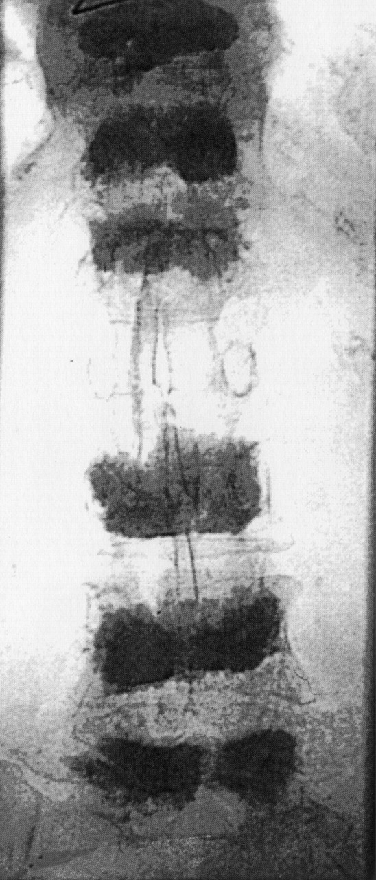
  • Fig 15.
    • Download figure
    • Open in new tab
    • Download powerpoint
    Fig 15.

    Anterioposterior radiograph showing six vertebrae treated with vertebroplasty. Ultimately, 10 levels were treated in this patient.

Tables

  • Figures
    • View popup
    TABLE 1:

    Vertebroplasty complications

    Cement leaks:
     Should be of no consequence if small
     Large leaks may cause local or radicular pain, neurologic damage, pulmonary embolus, or death
    Inaccurate needle placement:
     Injury to nerve root or spinal cord
     Injury to adjacent organs (eg lungs)
    Pain exacerabation:
     May occur due to substantial leaks into adjacent tissue or veins
     May occur without leak (transient pain flair)
    Infection (rare)
    Bleeding (rare without coagulopathy or anticoagulation)
    • View popup
    TABLE 2:

    “No-Sting” Anesthetic Mixture

    SolutionComposition
    Solution 1: 0.5% lidocaineaLidocaine 4% (4 cc); lactated ringer’s (24 cc); bicarbonate (2 cc); epinephrine (0)
    Solution 2: 0.5% lidocaine with epinephrineaLidocaine 4% (4 cc); lactated ringer’s (24 cc); bicarbonate (2 cc); epinephrine (0.15 cc of 1:1,000)
    • a This solution is preservative free and should be discarded at the end of each workday.

PreviousNext
Back to top

In this issue

American Journal of Neuroradiology: 24 (8)
American Journal of Neuroradiology
Vol. 24, Issue 8
1 Sep 2003
  • Table of Contents
  • Index by author
Advertisement
Print
Download PDF
Email Article

Thank you for your interest in spreading the word on American Journal of Neuroradiology.

NOTE: We only request your email address so that the person you are recommending the page to knows that you wanted them to see it, and that it is not junk mail. We do not capture any email address.

Enter multiple addresses on separate lines or separate them with commas.
Percutaneous Vertebroplasty: Complication Avoidance and Technique Optimization
(Your Name) has sent you a message from American Journal of Neuroradiology
(Your Name) thought you would like to see the American Journal of Neuroradiology web site.
CAPTCHA
This question is for testing whether or not you are a human visitor and to prevent automated spam submissions.
Cite this article
John M. Mathis
Percutaneous Vertebroplasty: Complication Avoidance and Technique Optimization
American Journal of Neuroradiology Sep 2003, 24 (8) 1697-1706;

Citation Manager Formats

  • BibTeX
  • Bookends
  • EasyBib
  • EndNote (tagged)
  • EndNote 8 (xml)
  • Medlars
  • Mendeley
  • Papers
  • RefWorks Tagged
  • Ref Manager
  • RIS
  • Zotero
0 Responses
Respond to this article
Share
Bookmark this article
Percutaneous Vertebroplasty: Complication Avoidance and Technique Optimization
John M. Mathis
American Journal of Neuroradiology Sep 2003, 24 (8) 1697-1706;
del.icio.us logo Twitter logo Facebook logo Mendeley logo
  • Tweet Widget
  • Facebook Like
  • Google Plus One

Jump to section

  • Article
    • Complication Avoidance
    • Technique Optimization
    • Conclusion
    • References
  • Figures & Data
  • Info & Metrics
  • Responses
  • References
  • PDF

Related Articles

  • No related articles found.
  • PubMed
  • Google Scholar

Cited By...

  • Pulmonary cement embolisation after percutaneous vertebroplasty
  • Republished: Retained needle after cement injection during vertebral augmentation and its management strategy
  • Use and evaluation of a semi-permeable mesh implant in vertebral augmentation for the treatment of painful osteoporotic vertebral compression fractures
  • Retained needle after cement injection during vertebral augmentation and its management strategy
  • Kyphoplasty and Vertebroplasty Produce the Same Degree of Height Restoration
  • Crossref
  • Google Scholar

This article has not yet been cited by articles in journals that are participating in Crossref Cited-by Linking.

More in this TOC Section

  • Management Outcomes For VO Spine Biopsy
  • Cone Beam CT Myelography
  • Post-Procedural Brachial Neuritis Features
Show more Spine Imaging and Spine Image-Guided Interventions

Similar Articles

Advertisement

Indexed Content

  • Current Issue
  • Accepted Manuscripts
  • Article Preview
  • Past Issues
  • Editorials
  • Editor's Choice
  • Fellows' Journal Club
  • Letters to the Editor
  • Video Articles

Cases

  • Case Collection
  • Archive - Case of the Week
  • Archive - Case of the Month
  • Archive - Classic Case

More from AJNR

  • Trainee Corner
  • Imaging Protocols
  • MRI Safety Corner
  • Book Reviews

Multimedia

  • AJNR Podcasts
  • AJNR Scantastics

Resources

  • Turnaround Time
  • Submit a Manuscript
  • Submit a Video Article
  • Submit an eLetter to the Editor/Response
  • Manuscript Submission Guidelines
  • Statistical Tips
  • Fast Publishing of Accepted Manuscripts
  • Graphical Abstract Preparation
  • Imaging Protocol Submission
  • Evidence-Based Medicine Level Guide
  • Publishing Checklists
  • Author Policies
  • Become a Reviewer/Academy of Reviewers
  • News and Updates

About Us

  • About AJNR
  • Editorial Board
  • Editorial Board Alumni
  • Alerts
  • Permissions
  • Not an AJNR Subscriber? Join Now
  • Advertise with Us
  • Librarian Resources
  • Feedback
  • Terms and Conditions
  • AJNR Editorial Board Alumni

American Society of Neuroradiology

  • Not an ASNR Member? Join Now

© 2025 by the American Society of Neuroradiology All rights, including for text and data mining, AI training, and similar technologies, are reserved.
Print ISSN: 0195-6108 Online ISSN: 1936-959X

Powered by HighWire