Article Figures & Data
Figures
fig. 1. Case 6.
A, Anteroposterior right vertebral angiogram shows a large wide-necked aneurysm at the basilar tip; B, lateral view of same; C, 3D reconstruction, lateral view, note width of neck in anteroposterior diameter; D, anteroposterior view of microcatheter, with coil ready for deployment, introduced into aneurysm via right VA; also visible is the remodeling balloon catheter with guidewire, introduced via the right ICA, then coursing through the PCom, right P1, and across the neck of the aneurysm, with the wire extending into the left P1 and P2; E, schematic illustration of catheter deployment; F, final phase of embolization, just before detachment of last coil (arrow on proximal marker of embolization catheter), with remodeling balloon inflated, anteroposterior view; G, lateral view of same, note how the top of the BA has been remodeled with the balloon, reconstructing the normal vascular lumen; H, final postembolization anteroposterior vertebral angiogram; I, same, lateral view, note the curve of the top of the BA and the proximal P1 due to balloon remodeling.
fig. 2. Case 4.
A, Skull radiograph, anteroposterior view, shows coils in previously embolized left ICA aneurysm; B, right anterior oblique projection of right ICA angiogram shows bilobate lateral-wall ICA aneurysm (wide arrow) and unilobar medial-wall aneurysm (thin arrow); C, 3D reconstruction, same view, shows bilobate lateral-wall aneurysm (large straight white arrow) and medial-wall aneurysm (small straight white arrow) of right ICA (curved arrow) as well as coil mass from embolized left ICA aneurysm (wide arrow), gray arrows are orientation markers from the reconstruction; D, same projection, higher magnification, shows nonsubtracted view of balloon and embolization catheters during embolization of anterior lobe of the lateral-wall aneurysm; the balloon catheter and wire are coming up the ICA and extending into the MCA (white arrows); the embolization catheter, which has a coil in it, comes up the right VA, into the BA, then into the right P1, PCom, ICA, and aneurysm (black arrows); E, schematic view shows course of balloon and embolization catheters in this case; F, post-embolization right ICA angiogram shows complete packing of the lateral wall ICA aneurysm; G, post-treatment skull radiograph, anteroposterior view, shows coils in right ICA bilobate aneurysm.
Tables

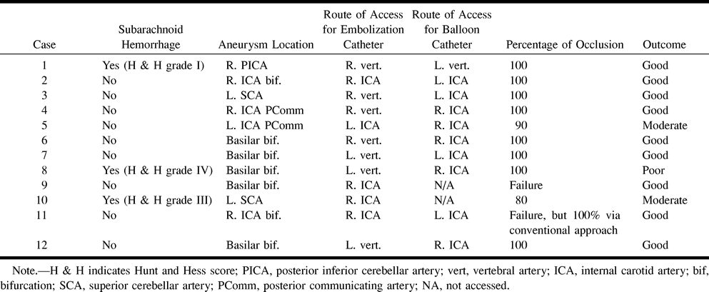
Data in 12 patients with cerebral aneurysms treated via nonanterograde approach


